

Manufacturing tolerances define the acceptable variation in a part. They help turn the exact dimensions shown in CAD into requirements a supplier can manufacture and inspect. For product teams, tolerances affect whether parts fit, controls move freely, seams look consistent, and assemblies can be repeated.
The important question is how much variation the product can accept while still working as intended. This guide introduces the main ideas through a simple example and a practical review process.
Understanding manufacturing tolerances
A nominal dimension is the intended size. A tolerance defines the permitted variation around it. For example, a fictional component specified as 20.00 mm ±0.10 mm can measure from 19.90 mm to 20.10 mm for that dimension.
Those limits describe one size requirement. They do not, by themselves, fully define the shape or position of every surface. A complete part definition needs to communicate the features that control function, along with how the finished part will be checked.
Clearance is a relationship between parts
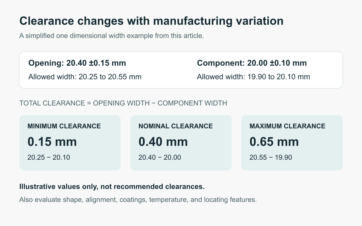
Imagine a rectangular component that must fit inside an opening. In a simplified one dimensional example, let the component width be 20.00 mm ±0.10 mm and the opening width be 20.40 mm ±0.15 mm.
- The nominal total clearance is 20.40 − 20.00 = 0.40 mm.
- The smallest total clearance is 20.25 − 20.10 = 0.15 mm.
- The largest total clearance is 20.55 − 19.90 = 0.65 mm.
These are illustrative values, not recommended clearances. They show why checking nominal CAD alone is insufficient. The real assembly must also account for feature shape, alignment, coatings, temperature, and the method used to locate the component. A positive width clearance does not guarantee assembly if another interface creates interference.
Understand the tolerance stack
A tolerance stack follows the dimensions and relationships that influence a result. In an enclosure, the visible position of a button might depend on the outer shell, PCB supports, PCB thickness, switch height, and button geometry.
Start by defining the result you need to control. Then trace its contributors through the assembly. A simple worst case analysis evaluates permitted extremes together. Statistical methods require appropriate assumptions and process information; they should not be used casually to dismiss an unfavorable worst case result.
A useful design review asks whether changing the locating arrangement could reduce the number of contributors. Locating two related features from a common functional reference may be more effective than tightening several unrelated dimensions.
Use functional references for dimensions
Datums provide references for defining and inspecting geometric relationships. Choose them around how the part locates and functions in the assembly. A drawing that is convenient to dimension on screen may still be difficult to manufacture or inspect consistently.
Geometric dimensioning and tolerancing, or GD&T, adds a defined language for requirements involving form, orientation, location, and related relationships. ASME Y14.5 is one established standard for communicating these requirements. Agree the applicable system and edition with the supplier, then apply its rules consistently.
Match tolerances to the manufacturing route
Printed, machined, molded, and fabricated parts do not share one universal tolerance. Material, geometry, feature size, process, and finishing all influence what is practical. Supplier capability must be reviewed against the actual part.
For example, Protolabs Network publishes different dimensional guidance for its printing and machining services. Treat such guidance as a starting point for a supplier discussion. Confirm any requirement beyond the quoted service before approving an order.
If your prototype uses a different process from production, review the tolerances again for the next build. A manually adjusted prototype can demonstrate a concept while concealing variation that would matter in a batch.
Protect the dimensions that control the experience
Identify interfaces where variation affects function or perceived quality. These may include moving clearances, connector alignment, sealing surfaces, mounting locations, and visible enclosure gaps. Define a measurable acceptance requirement for each critical result.
Avoid tightening every dimension as a substitute for this analysis. Review whether each limit is necessary, achievable, and inspectable. Ask the supplier which requirements drive extra operations or inspection, and consider design changes that achieve the same result with a more practical process.
Plan inspection before releasing the files
Specify what is measured, the reference setup, and any relevant part condition. Agree whether a dimensional report, functional gauge, assembly check, or other evidence is appropriate. For finished surfaces, clarify whether the requirement applies before or after coating.
Keep the CAD, drawings, material specification, and inspection requirements on the same revision. Our manufacturing preparation checklist covers the wider supplier package.
Review tolerances at the assembly level
Before ordering prototypes or approving tooling, trace the important fits, visible gaps, and moving interfaces through the complete product. Confirm the design intent, supplier capability, and planned inspection together.
Obi Designs provides mechanical CAD and design for manufacturing support for physical products and enclosures. Share your assembly and the fit or quality issue you need to resolve to discuss the next review.
No Comments
There are not comments on this post yet. Be the first one!