
Choosing between 3D printing and CNC machining starts with the question your prototype must answer. A model for checking grip and overall size has different needs from a part used to evaluate a bearing fit, repeated loading, or heat transfer.
Both processes can support product development. The useful comparison is between specific materials, geometry, finishes, and inspection requirements. This guide focuses on how founders and product teams can choose the next build with a clear purpose.
3D printing vs CNC machining: start with the test
Write a short acceptance statement before requesting quotes. For example: “Confirm that users can reach all controls while holding the device,” or “Check that the shaft and housing assemble within the specified fit.” Then identify which features must represent the intended product accurately.
If the test is about reach, mass, and proportion, you may be able to simplify internal geometry. If it is about friction or heat, the material and surface condition become central. Our prototype planning guide explains how to match the build to the decision.
Compare the actual materials
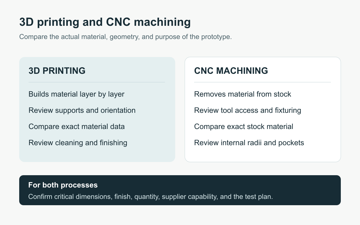
CNC machining removes material from stock, while 3D printing builds a part through an additive process. A machined thermoplastic and a printed resin with a similar marketing description should not be assumed to behave identically.
Check the exact material data for the proposed build. Ask about stiffness, impact behavior, temperature, moisture, and any exposure relevant to the test. Formlabs’ material selection guidance shows how material choice, print orientation, and post processing affect application suitability. Printed parts can serve demanding uses, but the process and preparation need to match the requirement.
Check whether the geometry suits the process
A milling tool needs access to the surfaces it cuts. Deep pockets, enclosed channels, thin features, and internal corners can affect the machining strategy. Additive processes can offer more freedom for some of these shapes, although supports, trapped material, cleaning access, and minimum feature sizes still need review.
Protolabs’ CNC design guide discusses geometry and material tradeoffs when moving between plastic printing and machining. Use supplier feedback on the actual model before treating either route as practical.
For an early enclosure, for example, you might print several external forms, then machine selected components when a particular interface or material becomes important to the next test. That is a proposed development strategy, rather than a rule that every project must follow.
Specify fit and finish where they matter
A smooth appearance does not prove dimensional accuracy. Identify the interfaces that control the test, such as a locating pin, connector opening, sliding surface, or fastener position. Ask the supplier to confirm how those features will be made and measured.
Protolabs Network’s manufacturing standards illustrate that dimensional limits vary by printing process, material, and feature size. A general service tolerance may not satisfy your specific assembly. Put critical requirements on the drawing and confirm acceptance before ordering.
For an appearance model, specify the intended cosmetic surfaces and acceptable support or tool marks. Painting, sanding, coatings, and other finishing steps should be included in both the quote and the test plan.
Compare the complete build cost
Request quotes for the same quantity, required date, material, finish, and inspection scope. Include preparation, support removal, secondary machining, hardware installation, assembly, shipping, and expected revisions where relevant. A low price for unfinished parts can be a poor comparison with a quote that includes a completed assembly.
Also consider the cost of learning. If the geometry is likely to change after a user review, an economical first model may be sensible. If an unrepresentative material would invalidate the planned test, a cheaper part could leave you paying for the same question twice.
Keep the intended production method in view
A prototype that works does not automatically establish that the production method will work. If the final enclosure will be injection molded, review draft, wall sections, part splits, assembly, and tooling access during development. Our injection molding design guide covers those decisions.
Record any deliberate differences between the prototype and the planned product. These could include material, joining method, surface treatment, or geometry simplified for the build. The review team should know which conclusions can reasonably carry forward.
Choose the next build around one clear decision
- Use a quick form model when the immediate question is size, reach, or layout.
- Investigate machining when a particular stock material, interface, or surface is important to the test.
- Investigate a suitable printing process when geometry, iteration, or integrated features make it attractive.
- Use a combined assembly when different parts need different evidence.
Obi Designs helps teams connect CAD, prototype planning, and manufacturing decisions. Share your CAD, target material, and test question to define a practical next step before ordering parts.
No Comments
There are not comments on this post yet. Be the first one!